A summary of the optical system and features of BINGO can be found in the table below:
|
Primary reflector |
Off-axis paraboloid, 40 m in diameter |
|
Secondary reflector |
Off-axis hyperboloid, 36 m in diameter |
|
Effective focal length |
63.2 m |
|
FWHM |
0.67 ° (40 ‘) |
|
Number of horns |
28 (circular polarization) |
|
Horn opening |
1.9 m |
|
Horn length |
4.3 m |
|
Covered area in the sky |
~ 5300 deg² |
|
System Temperature |
70 K (non-cryogenic) |
|
Frequency band |
980 – 1260 MHz |
|
Redshift interval |
0.13 – 0.45 |
|
Channel resolution for FFT |
Undefined |
BINGO will make observations in the frequency range between 980 MHz and 1260 MHz. The lower cut in frequency (980 MHz) is to minimize the RFI, reducing the interference of cell phone signals (between 700-956 MHz).
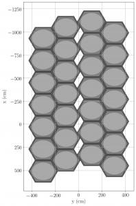
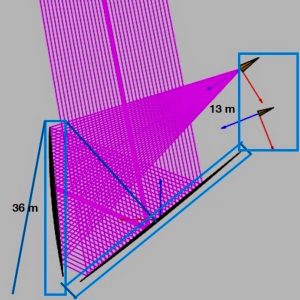
The BINGO radio telescope privileges a concept that is complementary to interferometric radio telescopes: it will use, for the same reflector system, many detectors in the focal plane. In general, interferometers are made up of many reflectors and only one detector (or few) in the focal plane. Telescopes like BINGO have a clear advantage in the cost of manufacturing and maintenance, in addition to the fact that data processing is inherently simpler. The obvious disadvantage is that the collecting area of an interferometer will normally be much larger than that of a single telescope, and the consequent angular resolution, much better. A schematic diagram of the telescope, with a hexagonal arrangement of the horns and the optical system, appears in Figure 1. The orientation of the focal plane in relation to the sky and the local coordinates is shown in Figure 2.
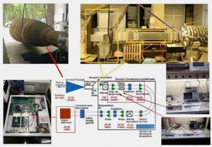
The construction of prototypes and testing of horns, as well as the radio telescope electronics, development, and testing of calibration and data reduction techniques, have been done by INPE – Brazil. The majority of BINGO’s components are produced/manufactured by the Brazillian national industry.
Figure 3 shows the BINGO receiver + horn scheme, with the block diagram in the center. The digital backend (red rectangle at the bottom left of the block diagram) will perform the fast Fourier transform (FFT) of the signal sent by the receiver chain, separating them into different channels between 980 and 1260 MHz. This number will still be defined.